Sensors
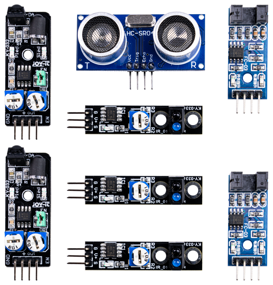
The Joy-Car is equipped with various sensors that enable versatile functions. These sensors include obstacle sensors that detect nearby objects and help the Joy-Car to avoid collisions. Line trackers are also present, allowing the Joy-Car to detect and follow lines or paths on the ground, which is particularly useful for applications such as following a track. In addition, the Joy-Car has speed sensors that measure the turning speed of the wheels, enabling precise motion control and speed monitoring. The sensor technology is supplemented by ultrasonic sensors that measure distances to objects and help to navigate and avoid obstacles. The combination of these sensors makes the Joy-Car a versatile vehicle that is suitable for both autonomous driving and interactive control tasks.
You can also find out more about the technical background of the sensors here.
Obstacle sensor
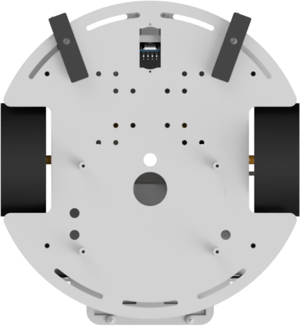
First, let's take a look at the obstacle sensors on the Joy-Car. These are located at the front on the sides and help to detect obstacles in the vicinity. This means that the Joy-Car can already detect when something is in the way. Later, we will even learn to avoid obstacles with these sensors, which is a big step towards autonomous driving.
In this code example, we use the obstacle sensors to indicate where an obstacle is located. If only the left sensor detects an obstacle, an arrow pointing to the left is displayed on the micro:bit. The same happens if the right sensor detects an obstacle - then the arrow points to the right. If obstacles are detected by both sensors at the same time, the micro:bit displays an arrow pointing straight ahead. So we always know exactly where something is in the way!
Check obstacle sensor

Checks the left/right obstacle sensor to see if an obstacle has been detected. The function returns True or False as the answer.
Code example
JoyCar.initJoyCar(RevisionMainboard.OnepThree)
basic.forever(function () {
    if (JoyCar.obstacleavoidance(SensorLRSelection.Left) && JoyCar.obstacleavoidance(SensorLRSelection.Right)) {
        serial.writeLine("Obstacle detected at the front")
        basic.showLeds(`
            . . # . .
            . . # . .
            # . # . #
            . # # # .
            . . # . .
            `)
        basic.pause(500)
    } else if (!(JoyCar.obstacleavoidance(SensorLRSelection.Left)) && JoyCar.obstacleavoidance(SensorLRSelection.Right)) {
        serial.writeLine("Obstacle detected on the left-hand side")
        basic.showLeds(`
            . . . . #
            # . . # .
            # . # . .
            # # . . .
            # # # # .
            `)
        basic.pause(500)
    } else if (JoyCar.obstacleavoidance(SensorLRSelection.Left) && !(JoyCar.obstacleavoidance(SensorLRSelection.Right))) {
        serial.writeLine("Obstacle detected on the right-hand side")
        basic.showLeds(`
            # . . . .
            . # . . #
            . . # . #
            . . . # #
            . # # # #
            `)
        basic.pause(500)
    } else {
        basic.clearScreen()
    }
})Retrieve sensor data
First, we want to read the data from the fetchSensorData method. To do this, we create an array called sensor_data, in which the information returned by the method is stored. This array enables us to specifically access the sensor data and process it further in our program.
# Retrieve data from the IO expander
sensor_data = fetchSensorData()
Check obstacle sensor
Like all other sensors, the obstacle sensors are read out using the fetchSensorData method. The information on the individual sensors is stored in the returned array sensor_data.
The data for the left-hand obstacle sensor is located at position 5 of the array, while the data for the right-hand obstacle sensor is stored at position 6. If, for example, the value False is stored at position 5 of the array, this means that the left-hand obstacle sensor has detected an obstacle. If, on the other hand, the value is True, the sensor does not detect an obstacle. The same applies to the 6th position, which indicates the status of the right-hand obstacle sensor.
# Check whether both sensors detect an obstacle
if sensor_data[5] is False and sensor_data[6] is False:
    print("Obstacle detected at the front")
    # Show arrow on the LED matrix in this direction
    display.show(front)
    sleep(500)
Code example
# Import necessary libraries
from microbit import *

# Define your Joy-Car mainboard revision
joycar_rev = 1.3

# Initialization of the I2C interface for the Joy-Car mainboard
i2c.init(freq=400000, sda=pin20, scl=pin19)

# retrieve all sensor data
def fetchSensorData():
    # Since the zfill function is not included in micro:bit Micropython,
    # it must be inserted as a function
    def zfill(s, width):
        return '{:0>{w}}'.format(s, w=width)

    # Read hexadecimal data and convert to binary data
    data = "{0:b}".format(ord(i2c.read(0x38, 1)))
    # Fill in the data to 8 digits if required
    data = zfill(data, 8)
    # declare bol_data_dict as dictionary
    bol_data_dict = {}
    # Counter for the loop that enters the data from data into bol_data_dict
    bit_count = 7
    # Transfer the data from data to bol_data_dict
    for i in data:
        if i == "0":
            bol_data_dict[bit_count] = False
            bit_count -= 1
        else:
            bol_data_dict[bit_count] = True
            bit_count -= 1

    # As of mainboard revision 1.3, the speed sensors are on separate pins
    if joycar_rev >= 1.3:
        bol_data_dict[8], bol_data_dict[9] = bol_data_dict[0], bol_data_dict[1]
        bol_data_dict[0] = bool(pin14.read_digital())
        bol_data_dict[1] = bool(pin15.read_digital())

    # bit 0 = SpeedLeft, bit 1 = SpeedRight, bit 2 = LineTrackerLeft,
    # bit 3 = LinetrackerCenter, bit 4 = LinetrackerRight,
    # bit 5 = ObstacleLeft, bit 6 = ObstacleRight, bit 7 = free pin(7)
    # (bit 8 = free (pin0) bit 9 = free (pin1)) - only with revision 1.3 or newer
    return bol_data_dict

# Define images to be displayed on the LED matrix
right = Image("00009:"
              "90090:"
              "90900:"
              "99000:"
              "99990")
left = Image("90000:"
             "09009:"
             "00909:"
             "00099:"
             "09999")
front = Image("00900:"
              "00900:"
              "90909:"
              "09990:"
              "00900")

while True:
    # Retrieve data from the IO expander
    sensor_data = fetchSensorData()

    # Check whether both sensors detect an obstacle
    if sensor_data[5] is False and sensor_data[6] is False:
        print("Obstacle detected at the front")
        # Show arrow on the LED matrix in this direction
        display.show(front)
        sleep(500)
    # Check whether an obstacle is detected on the left-hand side
    elif sensor_data[5] is False and sensor_data[6] is True:
        print("Obstacle detected on the left-hand side")
        # Show arrow on the LED matrix in this direction
        display.show(left)
        sleep(500)
    # Check whether an obstacle is detected on the right-hand side
    elif sensor_data[6] is False and sensor_data[5] is True:
        print("Obstacle detected on the right-hand side")
        # Show arrow on the LED matrix in this direction
        display.show(right)
        sleep(500)
    else:
        # Clear LED matrix
display.clear()Check obstacle sensor
Checks the left/right obstacle sensor to see if an obstacle has been detected. The function returns True or False as the answer.
Code example
JoyCar.initJoyCar(RevisionMainboard.OnepThree)
JoyCar.initController(ControllerType.Calliope)
basic.forever(function () {
    if (JoyCar.obstacleavoidance(SensorLRSelection.Left) && JoyCar.obstacleavoidance(SensorLRSelection.Right)) {
        serial.writeLine("Obstacle detected at the front")
        basic.showLeds(`
            . . # . .
            . . # . .
            # . # . #
            . # # # .
            . . # . .
            `)
        basic.pause(500)
    } else if (!(JoyCar.obstacleavoidance(SensorLRSelection.Left)) && JoyCar.obstacleavoidance(SensorLRSelection.Right)) {
        serial.writeLine("Obstacle detected on the left-hand side")
        basic.showLeds(`
            . . . . #
            # . . # .
            # . # . .
            # # . . .
            # # # # .
            `)
        basic.pause(500)
    } else if (JoyCar.obstacleavoidance(SensorLRSelection.Left) && !(JoyCar.obstacleavoidance(SensorLRSelection.Right))) {
        serial.writeLine("Obstacle detected on the right-hand side")
        basic.showLeds(`
            # . . . .
            . # . . #
            . . # . #
            . . . # #
            . # # # #
            `)
        basic.pause(500)
    } else {
        basic.clearScreen()
    }
})
Line tracker
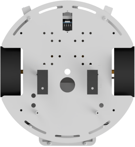
Now we come to the line tracker. These are located under the Joy-Car and there are three of them in total. They are there to detect when the Joy-Car deviates from a line. In later projects, they can be used to ensure that the Joy-Car automatically follows a black line and thus moves along a predefined route.
Check line tracker

Checks the left/center/right linetracker to see if a line could be detected on the floor. The function returns True or False as the response.
Code example
JoyCar.initJoyCar(RevisionMainboard.OnepThree)
basic.forever(function () {
    if (!(JoyCar.linefinder(SensorLCRSelection.Left)) && (JoyCar.linefinder(SensorLCRSelection.Center) && JoyCar.linefinder(SensorLCRSelection.Right))) {
        serial.writeLine("Line discovered on the left-hand side")
        basic.showLeds(`
            . . . . #
            . . . . #
            . . . . #
            . . . . #
            . . . . #
            `)
    } else if (JoyCar.linefinder(SensorLCRSelection.Left) && (!(JoyCar.linefinder(SensorLCRSelection.Center)) && JoyCar.linefinder(SensorLCRSelection.Right))) {
        serial.writeLine("Line discovered in the center")
        basic.showLeds(`
            . . # . .
            . . # . .
            . . # . .
            . . # . .
            . . # . .
            `)
    } else if (JoyCar.linefinder(SensorLCRSelection.Left) && (JoyCar.linefinder(SensorLCRSelection.Center) && !(JoyCar.linefinder(SensorLCRSelection.Right)))) {
        serial.writeLine("Line discovered on the right-hand side")
        basic.showLeds(`
            # . . . .
            # . . . .
            # . . . .
            # . . . .
            # . . . .
            `)
    } else {
        basic.clearScreen()
    }
})Retrieve sensor data
First, we want to read the data from the fetchSensorData method. To do this, we create an array called sensor_data, in which the information returned by the method is stored. This array allows us to specifically access the sensor data and process it further in our program.
# Retrieve data from the IO expander
sensor_data = fetchSensorData()
Check line tracker
The line sensors are also read out using the fetchSensorData method. The information on the individual sensors is stored in the returned array sensor_data.
The data of the left line sensor is located at position 2 of the array. The middle line sensor is stored at position 3, and the information from the right line sensor can be found at position 4.
If the value in position 2 of the array is False, this means that the left line sensor has detected a black area underneath it. The same applies to the middle and right line sensor: A False at the corresponding positions indicates that the respective sensor detects a black surface. A True indicates that there is a lighter area underneath.
# Check whether only the left sensor detects a line
if sensor_data[2] is True and sensor_data[3] is False and sensor_data[4] is False:
    print("Line discovered on the left-hand side")
    display.show(left)
Code example
# Import necessary libraries
from microbit import *

# Define your Joy-Car mainboard revision
joycar_rev = 1.3

# Initialization of the I2C interface for the Joy-Car mainboard
i2c.init(freq=400000, sda=pin20, scl=pin19)

# retrieve all sensor data
def fetchSensorData():
    # Since the zfill function is not included in micro:bit Micropython,
    # it must be inserted as a function
    def zfill(s, width):
        return '{:0>{w}}'.format(s, w=width)

    # Read hexadecimal data and convert to binary data
    data = "{0:b}".format(ord(i2c.read(0x38, 1)))
    # Fill in the data to 8 digits if required
    data = zfill(data, 8)
    # declare bol_data_dict as dictionary
    bol_data_dict = {}
    # Counter for the loop that enters the data from data into bol_data_dict
    bit_count = 7
    # Transfer the data from data to bol_data_dict
    for i in data:
        if i == "0":
            bol_data_dict[bit_count] = False
            bit_count -= 1
        else:
            bol_data_dict[bit_count] = True
            bit_count -= 1

    # As of mainboard revision 1.3, the speed sensors are on separate pins
    if joycar_rev >= 1.3:
        bol_data_dict[8], bol_data_dict[9] = bol_data_dict[0], bol_data_dict[1]
        bol_data_dict[0] = bool(pin14.read_digital())
        bol_data_dict[1] = bool(pin15.read_digital())

    # bit 0 = SpeedLeft, bit 1 = SpeedRight, bit 2 = LineTrackerLeft,
    # bit 3 = LinetrackerCenter, bit 4 = LinetrackerRight,
    # bit 5 = ObstacleLeft, bit 6 = ObstacleRight, bit 7 = free pin(7)
    # (bit 8 = free (pin0) bit 9 = free (pin1)) - only with revision 1.3 or newer
    return bol_data_dict

# Define images to be displayed on the LED matrix
right = Image("90000:"
              "90000:"
              "90000:"
              "90000:"
              "90000")
middle = Image("00900:"
               "00900:"
               "00900:"
               "00900:"
               "00900")
left = Image("00009:"
             "00009:"
             "00009:"
             "00009:"
             "00009")

while True:
    # Retrieve data from the IO expander
    sensor_data = fetchSensorData()

    # Check whether only the left sensor detects a line
    if sensor_data[2] is True and sensor_data[3] is False and sensor_data[4] is False:
        print("Line discovered on the left-hand side")
        display.show(left)
    # Check whether only the middle sensor detects a line
    elif sensor_data[2] is False and sensor_data[3] is True and sensor_data[4] is False:
        print("Line discovered in the middle")
        display.show(middle)
    # Check whether only the right sensor detects a line
    elif sensor_data[2] is False and sensor_data[3] is False and sensor_data[4] is True:
        print("Line discovered on the right-hand side")
        display.show(right)
    else:
display.clear()Check line tracker
Checks the left/center/right linetracker to see if a line could be detected on the floor. The function returns True or False as the response.
Code example
JoyCar.initJoyCar(RevisionMainboard.OnepThree)
JoyCar.initController(ControllerType.Calliope)
basic.forever(function () {
    if (!(JoyCar.linefinder(SensorLCRSelection.Left)) && (JoyCar.linefinder(SensorLCRSelection.Center) && JoyCar.linefinder(SensorLCRSelection.Right))) {
        serial.writeLine("Line discovered on the left-hand side")
        basic.showLeds(`
            . . . . #
            . . . . #
            . . . . #
            . . . . #
            . . . . #
            `)
    } else if (JoyCar.linefinder(SensorLCRSelection.Left) && (!(JoyCar.linefinder(SensorLCRSelection.Center)) && JoyCar.linefinder(SensorLCRSelection.Right))) {
        serial.writeLine("Line discovered in the center")
        basic.showLeds(`
            . . # . .
            . . # . .
            . . # . .
            . . # . .
            . . # . .
            `)
    } else if (JoyCar.linefinder(SensorLCRSelection.Left) && (JoyCar.linefinder(SensorLCRSelection.Center) && !(JoyCar.linefinder(SensorLCRSelection.Right)))) {
        serial.writeLine("Line discovered on the right-hand side")
        basic.showLeds(`
            # . . . .
            # . . . .
            # . . . .
            # . . . .
            # . . . .
            `)
    } else {
        basic.clearScreen()
    }
})
Speed sensors
The Joy-Car is also equipped with two speed sensors located next to the motors. These sensors measure the revolutions of the motors using a small wheel. By counting the revolutions, they can calculate the current speed. This is particularly useful for precisely setting an offset between the motors and ensuring that the Joy-Car drives straight ahead or exactly maintains a desired speed.
In the following example, the speeds of the two motors are calculated. To ensure that the Joy-Car does not drive off the desk, we recommend placing the vehicle on the parking bracket supplied. This allows the motors to be tested safely without the Joy-Car moving.
Check speed sensor

Checks the left/right speed sensor to see whether the signal has been interrupted by the perforated disk. The function returns True or False as the answer.
Revisions ≥ 1.3
Code example for revisions as of 1.3
In the Joy-Car from revision 1.3, the speed sensors from the IO expander are connected directly to the micro:bit. This allows the sensors to be read out faster and more precisely, which enables even more precise control and synchronization of the motors. This change significantly improves the performance of the Joy-Car, especially for projects that require precise speed control.
pins.onPulsed(DigitalPin.P15, PulseValue.High, function () {
    counter_right += 1
})
pins.onPulsed(DigitalPin.P14, PulseValue.High, function () {
    counter_left += 1
})
let speed_right = 0
let speed_left = 0
JoyCar.initJoyCar(RevisionMainboard.OnepThree)
let counter_left = 0
let counter_right = 0
let interval = 10
let wheel = 20
let calc = 60 / interval
let timer_start = control.millis()
JoyCar.drive(FRLRDirection.Forward, 100)
basic.forever(function () {
    if (control.millis() - timer_start >= interval * 1000) {
        speed_left = counter_left / 2 * calc / wheel
        speed_right = counter_right / 2 * calc / wheel
        serial.writeLine("Revolutions per minute left motor: " + speed_left)
        serial.writeLine("Revolutions per minute right motor: " + speed_right)
        counter_left = 0
        counter_right = 0
        timer_start = control.millis()
    }
})
Revision ≤ 1.2
Code example for revisions up to 1.2
In the latest Joy-Cars, the speed sensors are still connected to the IO expander. This has the disadvantage that the speed cannot be read out as precisely, as communication with the IO expander causes additional delays. This affects the accuracy of the speed measurement and therefore also the fine tuning of the motors.
Speed calculation
To calculate the speed, we need various variables that perform different tasks.
The constant variables include:
one_round: Specifies how many pulses are required for one complete rotation of the wheel.interval: Defines the time interval in which the speed is calculated.calc: Used to perform the calculations based on the recorded data.wheel: Refers to the wheel size or specific parameters of the wheels that are included in the calculation.
To record the actual revolutions of the wheels, we use the following variables:
timer_start: Holds the start time of the current interval.counter_leftandcounter_right: Count the pulses detected by the left and right speed sensors.
In addition, we need variables to recognize state changes:
left_lastandleft_current: Save the previous and current state of the left speed sensor.right_lastandright_current: Save the previous and current state of the right speed sensor.
# Set the number of steps for a round
one_round = 2056

# Definition of the necessary parameters for calculating the speed
counter = 0
interval = 10   # in seconds
calc = 60 / interval
wheel = 20
timer_start = running_time()

# Definition of specific parameters for the left and right speed sensors
counter_left = 0
counter_right = 0

# Define parameters to check whether the value changes
left_last = -1
left_current = -1
right_last = -1
right_current = -1
Control motors
In order for the speed to be calculated, the Joy-Car must be set in motion. The speed sensors only generate the necessary impulses when the car is moving, which can then be recorded by the variables and used to calculate the speed. During the test, it is important to either let the Joy-Car run in a controlled manner on the parking bracket or to ensure that it has enough space to drive freely.
# Set motors to forward drive
drive(0, 255, 0, 255)
Check speed sensor
Revisions ≥ 1.3
From revision 1.3, the speed sensors of the Joy-Car can be addressed directly via pins 14 and 15 of the micro:bit. This enables faster and more precise acquisition of the sensor data.
In order to measure the rotations of the wheels, it is also checked here whether the state of the sensors has changed. These state changes are caused by the holes in the wheel, which are detected by the sensors. As soon as 20 state changes have been counted, this corresponds exactly to one complete rotation of the wheel.
Thanks to the direct connection to the micro:bit, the delay caused by the IO expander is eliminated, which enables a more precise calculation of the speed.
# after mainboard revision 1.3 speed sensors are on separate pins
# and not on IO expanders
if joycar_rev >= 1.3:
    # Read value of pin 14
    left_current = pin14.read_digital()
    # Check whether the left speed sensor has changed its value
    if left_current != left_last:
        # Set last value to the current value
        left_last = left_current
        # Increase counter
        counter_left += 1
    # Read value of pin 15
    right_current = pin15.read_digital()
    # Check whether the right speed sensor has changed its value
    if right_current != right_last:
        # Set last value to the current value
        right_last = right_current
        # Increase counter
        counter_right += 1
Revisions ≤ 1.2
In older revisions of the Joy-Car, i.e. before version 1.3, the speed sensors are still connected to the IO expander. Therefore, the fetchSensorData method is used in these cases to read out the sensor data.
To measure the rotations of the wheels, the system checks whether the state of the sensors has changed. These state changes are caused by the holes in the wheel that are detected by the sensors. Once 20 state changes have been counted, this corresponds to a complete rotation of the wheel.
This method makes it possible to calculate the speed despite the limited precision of the IO expander.
else:
    """
    Reading data from the IO expander is very slow. For this reason, the
    rotations per minute are inaccurate. This can only be solved with newer revisions.
    """
    # Retrieve data from the IO expander
    sensor_data = fetchSensorData()
    # Read value from IO expander
    left_current = sensor_data[0]
    # Check whether the left speed sensor has changed its value
    if left_current != left_last:
        # Set last value to the current value
        left_last = left_current
        # Increase counter
        counter_left += 1
    # Read value from IO expander
    right_current = sensor_data[1]
    # Check whether the right-hand speed sensor has changed its value
    if right_current != right_last:
        # Set last value to the current value
        right_last = right_current
        # Increase counter
        counter_right += 1
Calculation of speed and output
After a period of 10 seconds, the measured speed is scaled up to one minute and displayed.
All variables used for the measurement are then reset, including the counters for the status changes and the timer. The measurement then starts again to continuously calculate and display current speeds.
# Check whether the set time interval has expired
if running_time() - timer_start >= interval * 1000:
    # Calculate rotations per minute
    speed_right = ((counter_right / 2) * calc) / wheel
    speed_left = ((counter_left / 2) * calc) / wheel
    # Output result
    print("Rotations per minute left motor: ", speed_left)
    print("Rotations per minute right motor: ", speed_right)
    # Reset parameters
    counter_left = 0
    counter_right = 0
    timer_start = running_time()
Code example
# Import necessary libraries
from microbit import *

# Define your Joy-Car mainboard revision
joycar_rev = 1.3

# Initialization of the I2C interface for the Joy-Car mainboard
i2c.init(freq=400000, sda=pin20, scl=pin19)

# Initialize PWM controller
i2c.write(0x70, b'\x00\x01')
i2c.write(0x70, b'\xE8\xAA')

# the delay of a motor deceleration can be used to compensate for different motor speeds
biasR = 0  # Deceleration of the right motor in percent
biasL = 0  # Deceleration of the left motor in percent

# Control motors with the PWM controller
# PWM0 and PWM1 for the left motor and PWM2 and PWM3 for the right motor
def drive(PWM0, PWM1, PWM2, PWM3):
    # The scaling function is used to scale the bias variables
    # for the calculation of the motor speed
    def scale(num, in_min, in_max, out_min, out_max):
        return (num - in_min) * (out_max - out_min) / (in_max - in_min) + out_min

    # Scaling of the delay value to the value in percent
    PWM0 = int(PWM0 * (scale(biasR, 0, 100, 100, 0) / 100))
    PWM1 = int(PWM1 * (scale(biasR, 0, 100, 100, 0) / 100))
    PWM2 = int(PWM2 * (scale(biasL, 0, 100, 100, 0) / 100))
    PWM3 = int(PWM3 * (scale(biasL, 0, 100, 100, 0) / 100))

    # Transmit value for PWM channel (0-255) to PWM controller
    # 0x70 is the I2C address of the controller
    # the byte with the PWM value is added to the byte for the channel
    i2c.write(0x70, b'\x02' + bytes([PWM0]))
    i2c.write(0x70, b'\x03' + bytes([PWM1]))
    i2c.write(0x70, b'\x04' + bytes([PWM2]))
    i2c.write(0x70, b'\x05' + bytes([PWM3]))

# retrieve all sensor data
def fetchSensorData():
    # Since the zfill function is not included in micro:bit Micropython,
    # it must be inserted as a function
    def zfill(s, width):
        return '{:0>{w}}'.format(s, w=width)

    # Read hexadecimal data and convert to binary data
    data = "{0:b}".format(ord(i2c.read(0x38, 1)))
    # Fill in the data to 8 digits if required
    data = zfill(data, 8)
    # declare bol_data_dict as dictionary
    bol_data_dict = {}
    # Counter for the loop that enters the data from data into bol_data_dict
    bit_count = 7
    # Transfer the data from data to bol_data_dict
    for i in data:
        if i == "0":
            bol_data_dict[bit_count] = False
            bit_count -= 1
        else:
            bol_data_dict[bit_count] = True
            bit_count -= 1

    # As of mainboard revision 1.3, the speed sensors are on separate pins
    if joycar_rev >= 1.3:
        bol_data_dict[8], bol_data_dict[9] = bol_data_dict[0], bol_data_dict[1]
        bol_data_dict[0] = bool(pin14.read_digital())
        bol_data_dict[1] = bool(pin15.read_digital())

    # bit 0 = SpeedLeft, bit 1 = SpeedRight, bit 2 = LineTrackerLeft,
    # bit 3 = LinetrackerCenter, bit 4 = LinetrackerRight,
    # bit 5 = ObstacleLeft, bit 6 = ObstacleRight, bit 7 = free pin(7)
    # (bit 8 = free (pin0) bit 9 = free (pin1)) - only with revision 1.3 or newer
    return bol_data_dict

# Set the number of steps for a round
one_round = 2056

# Definition of the necessary parameters for calculating the speed
counter = 0
interval = 10   # in seconds
calc = 60 / interval
wheel = 20
timer_start = running_time()

# Definition of specific parameters for the left and right speed sensors
counter_left = 0
counter_right = 0

# Define parameters to check whether the value changes
left_last = -1
left_current = -1
right_last = -1
right_current = -1

# Set motors to forward drive
drive(0, 255, 0, 255)

while True:
    # after mainboard revision 1.3 speed sensors are on separate pins
    # and not on IO expanders
    if joycar_rev >= 1.3:
        # Read value of pin 14
        left_current = pin14.read_digital()
        # Check whether the left speed sensor has changed its value
        if left_current != left_last:
            # Set last value to the current value
            left_last = left_current
            # Increase counter
            counter_left += 1
        # Read value of pin 15
        right_current = pin15.read_digital()
        # Check whether the right speed sensor has changed its value
        if right_current != right_last:
            # Set last value to the current value
            right_last = right_current
            # Increase counter
            counter_right += 1
    else:
        """
        Reading data from the IO expander is very slow. For this reason, the
        rotations per minute are inaccurate. This can only be solved with newer revisions.
        """
        # Retrieve data from the IO expander
        sensor_data = fetchSensorData()
        # Read value from IO expander
        left_current = sensor_data[0]
        # Check whether the left speed sensor has changed its value
        if left_current != left_last:
            # Set last value to the current value
            left_last = left_current
            # Increase counter
            counter_left += 1
        # Read value from IO expander
        right_current = sensor_data[1]
        # Check whether the right-hand speed sensor has changed its value
        if right_current != right_last:
            # Set last value to the current value
            right_last = right_current
            # Increase counter
            counter_right += 1

    # Check whether the set time interval has expired
    if running_time() - timer_start >= interval * 1000:
        # Calculate rotations per minute
        speed_right = ((counter_right / 2) * calc) / wheel
        speed_left = ((counter_left / 2) * calc) / wheel
        # Output result
        print("Rotations per minute left motor: ", speed_left)
        print("Rotations per minute right motor: ", speed_right)
        # Reset parameters
        counter_left = 0
        counter_right = 0
timer_start = running_time()Check speed sensor
Checks the left/right speed sensor to see whether the signal has been interrupted by the perforated disk. The function returns True or False as the answer.
Revisions ≥ 1.3
Code example for revisions as of 1.3
In the Joy-Car from revision 1.3, the speed sensors from the IO expander are connected directly to the micro:bit. This allows the sensors to be read out faster and more precisely, which enables even more precise control and synchronization of the motors. This change significantly improves the performance of the Joy-Car, especially for projects that require precise speed control.
pins.onPulsed(DigitalPin.C15, PulseValue.High, function () {
    counter_right += 1
})
pins.onPulsed(DigitalPin.C14, PulseValue.Low, function () {
    counter_left += 1
})
let speed_right = 0
let speed_left = 0
let counter_left = 0
let counter_right = 0
JoyCar.initJoyCar(RevisionMainboard.OnepThree)
JoyCar.initController(ControllerType.Calliope)
let interval = 10
let wheel = 20
let calc = 60 / interval
let timer_start = control.millis()
JoyCar.drive(FRLRDirection.Forward, 100)
basic.forever(function () {
    if (control.millis() - timer_start >= interval * 1000) {
        speed_left = counter_left / 2 * calc / wheel
        speed_right = counter_right / 2 * calc / wheel
        serial.writeLine("Umdrehungen pro Minute linker Motor: " + speed_left)
        serial.writeLine("Umdrehungen pro Minute rechter Motor: " + speed_right)
        counter_left = 0
        counter_right = 0
        timer_start = control.millis()
    }
})
Revision ≤ 1.2
Code example for revisions up to 1.2
In the latest Joy-Cars, the speed sensors are still connected to the IO expander. This has the disadvantage that the speed cannot be read out as precisely, as communication with the IO expander causes additional delays. This affects the accuracy of the speed measurement and therefore also the fine tuning of the motors.
Ultrasonic sensor
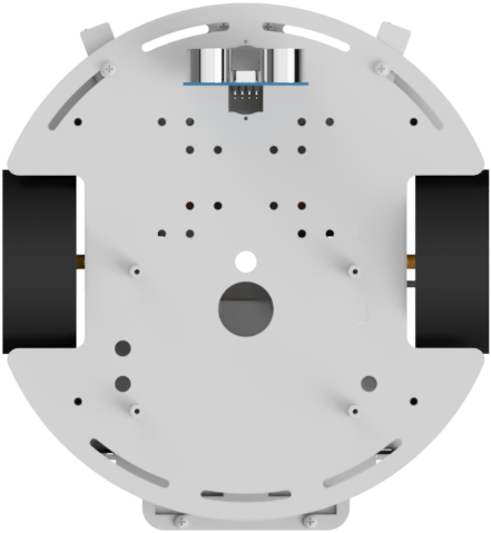
Finally, there is the ultrasonic sensor, which is located at the front of the Joy-Car. This sensor uses ultrasonic waves to measure the distance to objects in front of the vehicle. The sensor emits sound waves and measures the time it takes for the sound to be reflected back to the sensor by an obstacle. The distance can be precisely calculated from this time. The ultrasonic sensor is ideal for detecting obstacles and calculating distances.
In the following example, the ultrasonic sensor outputs its measured values at intervals of 500 milliseconds. This means that a new measurement is carried out every half a second and the distance determined is output. This allows continuous changes in the distance to objects in front of the Joy-Car to be tracked.
Check ultrasonic sensor

Checks the ultrasonic sensor for the distance to the nearest detected object. The function returns the distance as the response.
Code example
JoyCar.initJoyCar(RevisionMainboard.OnepThree)
basic.forever(function () {
    serial.writeLine("" + (Math.round(JoyCar.sonar())))
    basic.pause(500)
})Initialize ultrasonic sensor
First, the pins for the ultrasonic sensor must be defined. The sensor uses two pins:
- Trigger pin: This pin is used to send the ultrasonic signal. It initiates the sound wave emitted by the sensor.
- Echo pin: This pin measures when the ultrasonic signal returns after it has been reflected by an object.
By combining these two pins, the transmission time and the return time can be recorded in order to calculate the distance precisely.
# Define pins for ultrasonic sensor
trigger = pin8
echo = pin12

# Initialization of the pins for the ultrasonic sensor
trigger.write_digital(0)
echo.read_digital()
Ultrasonic sensor measure distance
The measured distance is calculated in the get_distance method and returned as a result.
First, the ultrasonic sensor emits an ultrasonic pulse via the trigger pin. At the same time, the echo pin is monitored to measure the time it takes for the signal to return after it has been reflected by an object.
The method uses the measured time between sending and receiving the signal to calculate the distance. The speed of sound in the air is taken into account to determine the exact distance in front of the ultrasonic sensor.
This calculation provides the distance in centimeters, which is then returned.
# Method for calculating the distance from the ultrasonic sensor
def get_distance():
    # Activate garbage collector
    gc.collect()
    # Set a short pulse on the trigger pin
    trigger.write_digital(1)
    trigger.write_digital(0)
    # Measurement of the time until the echo pin becomes high
    duration = time_pulse_us(echo, 1)
    # Calculate distance
    distance = ((duration / 1000000) * 34300) / 2
    # Return the distance, rounded to 2 decimal places
    return round(distance, 2)
Code example
# Import necessary libraries
from microbit import *
import gc
from machine import time_pulse_us

# Define your Joy-Car mainboard revision
joycar_rev = 1.3

# Define pins for ultrasonic sensor
trigger = pin8
echo = pin12

# Initialization of the pins for the ultrasonic sensor
trigger.write_digital(0)
echo.read_digital()

# Method for calculating the distance from the ultrasonic sensor
def get_distance():
    # Activate garbage collector
    gc.collect()
    # Set a short pulse on the trigger pin
    trigger.write_digital(1)
    trigger.write_digital(0)
    # Measurement of the time until the echo pin becomes high
    duration = time_pulse_us(echo, 1)
    # Calculate distance
    distance = ((duration / 1000000) * 34300) / 2
    # Return the distance, rounded to 2 decimal places
    return round(distance, 2)

while True:
    # Output of the measured distance from the ultrasonic sensor
    print(get_distance())
    # wait 500 ms
sleep(500)Check ultrasonic sensor
Checks the ultrasonic sensor for the distance to the nearest detected object. The function returns the distance as the response.
Code example
JoyCar.initJoyCar(RevisionMainboard.OnepThree)
JoyCar.initController(ControllerType.Calliope)
basic.forever(function () {
    serial.writeLine("" + (Math.round(JoyCar.sonar())))
    basic.pause(500)
})