The Joy-Car combines a variety of innovative sensors and modules that enable precise control and interaction. The most important sensors include ultrasonic and infrared technologies that can detect objects, avoid obstacles, follow lines and measure speed. The ultrasonic sensor measures distances of up to 300 cm and enables precise navigation. Obstacle, line tracking and speed sensors use infrared light to detect objects or surfaces and record movement data. The sensitivity of the sensors can be individually adjusted to achieve optimum results. Potentiometers and integrated LEDs help to visualize the detection status.
Central control units such as the IO expander and the PWM controller ensure efficient communication and control of the components via the I²C interface. The IO expander provides additional room for expansion and optimizes the use of the micro:bit's limited ports, while the PWM controller controls the speed, direction of rotation and braking modes of the motors. Addressable RGB LEDs serve as headlights and can be individually controlled to realize creative lighting effects.
The mainboard offers a wide range of configuration options such as the activation of additional pins, the simple disconnection of the power supply via a switch and the use of alternative voltage sources. A clear schematic diagram shows the connection between the components and the micro:bit, making it easy to implement customizations and your own projects. With these extensive functions and customization options, the Joy-Car is an ideal platform for technology enthusiasts who want to experiment, learn and program.
Sensors
Ultrasonic sensor

The ultrasonic sensor can be used with the Joy-Car for the detection of objects and obstacles in a range between 2 and 300 cm. Therefore, it can avoid obstacles with a bigger distance or even can ride towards the objects. The ultrasonic sensor is capable of measuring distances precisely, as it sends out highly frequent acoustic pulses. When the pulse hits an object, the sound is reflected. The reflected echo is detected by the sensor. The distance to the object can be calculated by the time span between sending and receiving the ultrasonic pulse.
The obstacle sensor, the linetracking sensor and the speed sensor all work on the same principle: infrared. The sensors use an infrared LED and an infrared receiver to detect the LED light.
OBSTACLE SENSOR

The obstacle sensor can detect objects in the vicinity of the Joy-Car. For this purpose, the LED emits infrared light to the front. If an object/obstacle comes into this light beam, the light is reflected and can be detected by the infrared receiver. The range of this sensor can be adjusted using the potentiometer. However, this sensor can only detect the distance preset by the potentiometers and cannot actively measure the distance to the nearest object like the ultrasonic sensor.

Adjust the obstacle sensors: First detach the chassis attachment from the base plate so that you can reach the potentiometers of the obstacle sensors more easily. In contrast to the line tracking sensors, the obstacle sensors each have two potentiometers. Here you can adjust both the strength of the infrared LED and the sensitivity of the sensor. Hold an object in front of the sensors. The LED should light up and go out again when you remove the object.
TIP: You can increase the sensitivity by turning the potentiometer clockwise. If you turn it counterclockwise, you reduce the sensitivity.
Linetracking sensor

The linetracking sensor emits the infrared light downwards. If there is a bright surface under the linetracking sensor, the light is reflected and detected by the infrared receiver. However, if the infrared light is shone onto a black and non-reflective surface, no infrared light is reflected back for the infrared receiver to detect. To follow a line, at least 2 sensors, but preferably 3 sensors, are required. With the help of 3 sensors, you are then able to determine where the black line is and in which direction you have to steer to follow it.
Set the line tracking sensors: It is best to take a white sheet of paper and stick a strip of black adhesive tape on it. Now place your Joy-Car alternately on the sheet of paper and on the black adhesive strip. Your sensors are set correctly when the LED on each sensor lights up when the Joy-Car is on the sheet of paper and when the LEDs go out again as soon as you place the Joy-Car on the adhesive strip.
Speed sensor

With the speed sensor, the infrared receiver and infrared LED are positioned directly opposite each other. The perforated disk, which is mounted on the motor shaft, is located between the receiver and the LED. If the motor shaft now rotates, the perforated disk also rotates. This repeatedly interrupts the infrared light of the LED. If you know the number of holes in the perforated disk (in this case 20), you know that the wheel has rotated 1/20 from interruption to interruption. Using this information, you can determine the distance traveled and if you add the time elapsed from interruption to interruption, you can determine the speed.
The sensitivity of the sensors can be adjusted if they no longer function reliably. The line tracking sensors and obstacle sensors are equipped with potentiometers that can be adjusted with a screwdriver to set the sensitivity. Each sensor is also fitted with an LED that only lights up when the sensor detects something. It helps you to check the function of your sensor and adjust it as well as possible.
I²C

The term I²C stands for Inter-Integrated Circuit, represents a serial data bus and describes how devices communicate with each other and exchange their data. The data is transmitted via two lines, the SDA (Serial Data) and the SCL (Serial Clock) line. The actual data is transmitted via the SDA line. The SCL line only specifies the clock frequency and signals when a bit is present on the data line. With the I2C bus, all devices communicate via the so-called master/slave principle. Here, all communication is controlled by a single device, the micro:bit (master), and all other devices simply wait for permission to send and are therefore called slaves. I²C is used in the Joy-Car for communication and control of the infrared sensors (IO expander) and the motor control unit (PWM controller).
FOR EXPERTS: Addresses 0x70 (PWM controller) and 0x38 (IO expander) are used to control the systems via I2C.
PWM

PWM stands for “Pulse Width Modulation”. With this method, the ratio of the switch-on time to the specified period duration is varied. Pulse width modulation is used to control the speed or brightness of loads such as motors or LEDs.
The duration of a period is usually a few milliseconds or less. In practical terms, this means that the corresponding load is switched on and off several hundred times per second. The longer the switch-on time in a period, the more energy can be transferred to the load. In other words, the longer the duty cycle, the faster the motor turns or the brighter the LED lights up. At 0% duty cycle, the load is off. Whereas at 100% duty cycle, the motor runs at full throttle and the LED lights up as brightly as possible.
Motors
The motors are controlled via the built-in PWM controller. Here, the speed can be regulated via the PWM signal (0-255), as well as the direction of rotation (forward & reverse) and the braking mode (strong & soft braking) can be set.
FOR EXPERTS: The PWM controller can be controlled via I2C using the address 0x70. A total of 4 channels (2, 3, 4 & 5) are available here for the two motors, which can be used as follows:
| Motor right channel 2 channel 3 |
Motor left channel 4 channel 5 |
Function |
||
| 0 | PWM | 0 | PWM | forwards |
| 0 | 0 | 0 | PWM | left |
| 0 | PWM | 0 | 0 | right |
| PWM | 0 | PWM | 0 | backwards |
| 255 | 255 | 255 | 255 | smooth braking |
| 0 | 0 | 0 | 0 | heavy braking |
Headlights

Addressable WS2812B RGB LEDs are used for the spotlights. A controller is built into each of these LEDs, which makes it possible to set the color and brightness for each LED individually. The data is transmitted to the first LED via a bus line connected to a pin on the micro:bit. This bus line is then continued from the first LED to the second LED, from the second LED to the third LED and so on. The data is then transmitted from LED to LED via this bus line. In other words, the LEDs form a kind of light chain in which each light can be controlled separately.
In the Joy-Car, this LED chain has been solved in such a way that 2 WS2812B LEDs are mounted on a headlight module. These two LEDs are already connected to the bus line on the circuit board. There is a “Din” (data in) and a “Dout” (data out) pin on the connection pins of the circuit board. These pins are used to connect the boards together. To keep the cabling clear, the LED boards are not connected directly to the bus line. The bus line is routed back to the mainboard of the Joy-Car and there from the “Dout” pin to the “Din” pin of the following LED module.
ATTENTION: If an LED module is not connected, the modules further down the chain will no longer work as the data connection is interrupted.
IO Expander

The IO expander is a central unit on your Joy-Car to which most of the sensors are connected. As the micro:bit does not have enough inputs for all sensors, these are connected to the IO expander. This then communicates with the micro:bit via the I2C interface. In this way, only two ports of the micro:bit are occupied. There are even unused digital outputs on the IO expander that you can use for your own projects and sensors. The IO expander is structured as follows:
FOR EXPERTS: The IO expander is addressed via the I2C address 0x38. It checks the sensors connected to it and returns the results summarized as bytes. Each bit represents a pin of the expander. If a corresponding detection is made, the bit of the sensor is set to 1 (True).

Mainboard

Revision
The Joy-Car is available in different revisions, which serve to identify the different versions of the vehicle. We are constantly working to improve the Joy-Car and therefore regularly make changes to the hardware. To find out which version of your Joy-Car you have, you can check the underside of the mainboard. The revision number is clearly visible there. If you cannot find a revision number, it is our first Joy-Car model 1.0. This information will help you to ensure compatibility with software projects and accessories.
The various revisions of the Joy-Car bring changes that improve the functionality and accuracy of the components:
Revision 1.0 till 1.2:
In these versions, the speed sensors are still connected directly to the IO expander. The measurements are functional, but less accurate due to the indirect processing.
Revision 1.3:
From this version onwards, the speed sensors are connected directly to the micro:bit. This change significantly improves the precision of the speed measurements. In addition, this change to the IO expander provides two further free digital outputs that can be used for additional functions.
These revisions show the continuous development of the Joy-Car to increase both the performance and the versatility of the hardware.
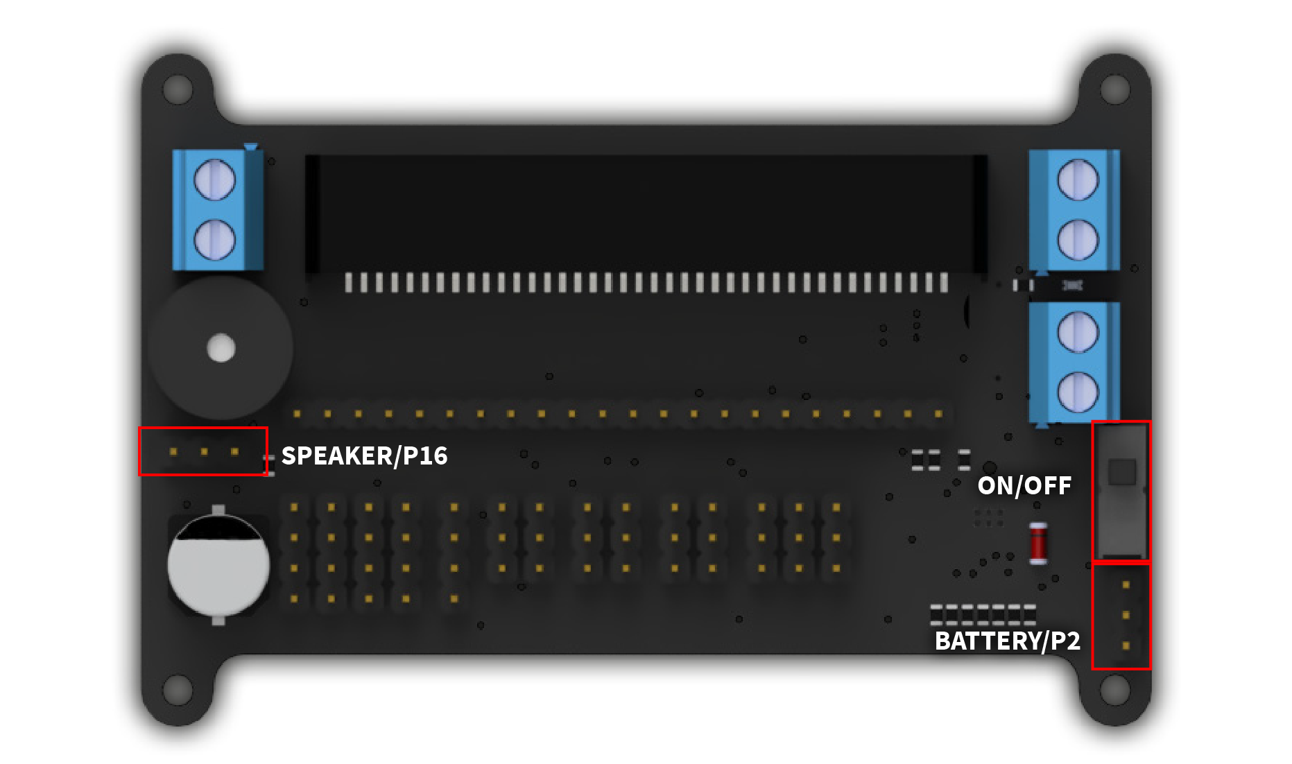
JUMPER
You can make further configurations on the mainboard of your Joy-Car using the jumpers. Here you can deactivate the speaker [SPK] and the battery voltage measurement [BAT] and thus activate pins P16 and P2 on the pin header of the mainboard. This allows you to activate two more pins for your own development if you need them.
ON/OFF
To switch your Joy-Car on or off, you don't have to keep inserting or removing the batteries. You can easily disconnect the power supply using the on/off switch.
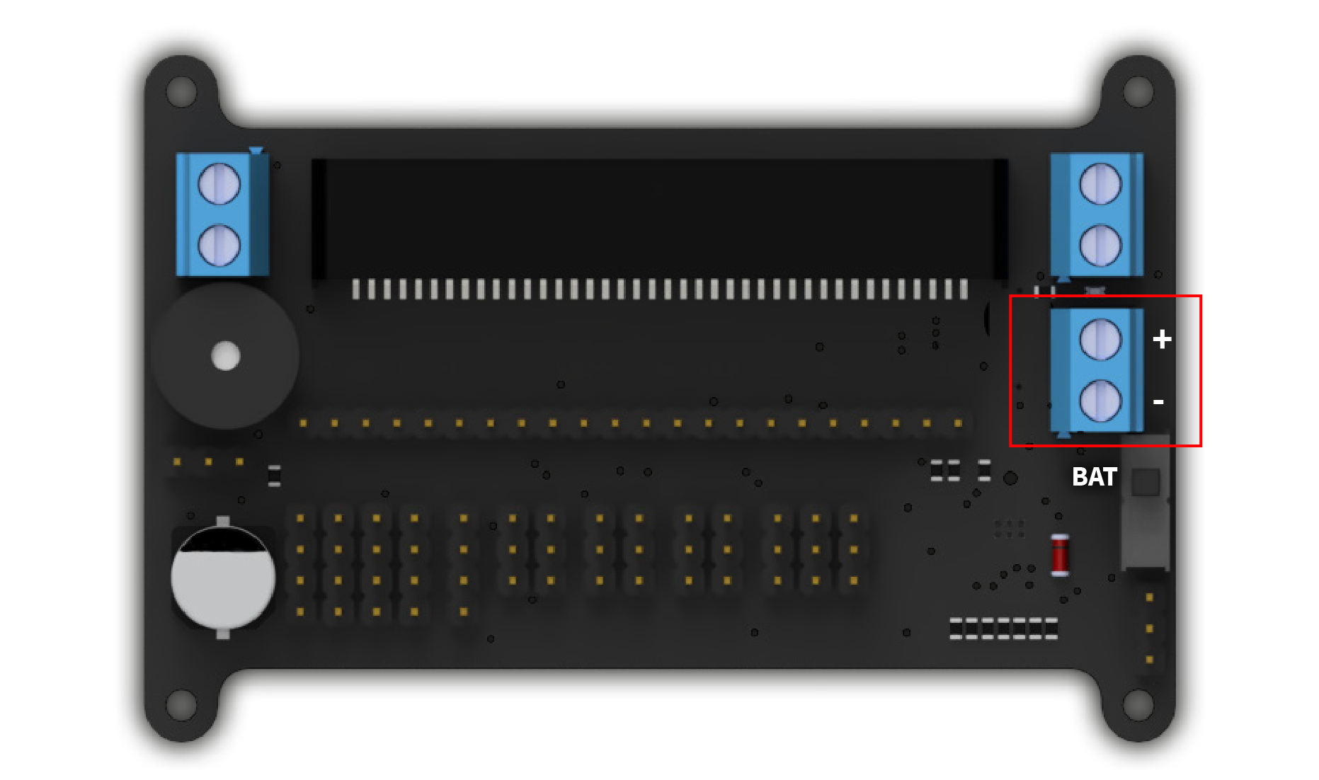
POWER SUPPLY
The installation instructions have already told you that you can connect the battery holder to the BAT terminal. However, if you want to make your own modifications, you are not tied to the battery holder. It is good to know here: You can connect any voltage source between 4.5-9 V to the BAT terminal.
Overview diagram
EVERYTHING IN THE RIGHT PLACE
The mainboard of the Joy-Car is of course only the connecting unit between the individual sensors and modules and the micro:bit. Would you like to know where and how the individual units are connected to the micro:bit? Or perhaps you would even like to make changes yourself? We have summarized all the units in our schematic diagram and show you how they are controlled by the micro:bit.
You can find out which revision your Joy-Car has here. There you will find detailed information on how to identify the revision of your Joy-Car and the differences between the revisions.

