IO Expander
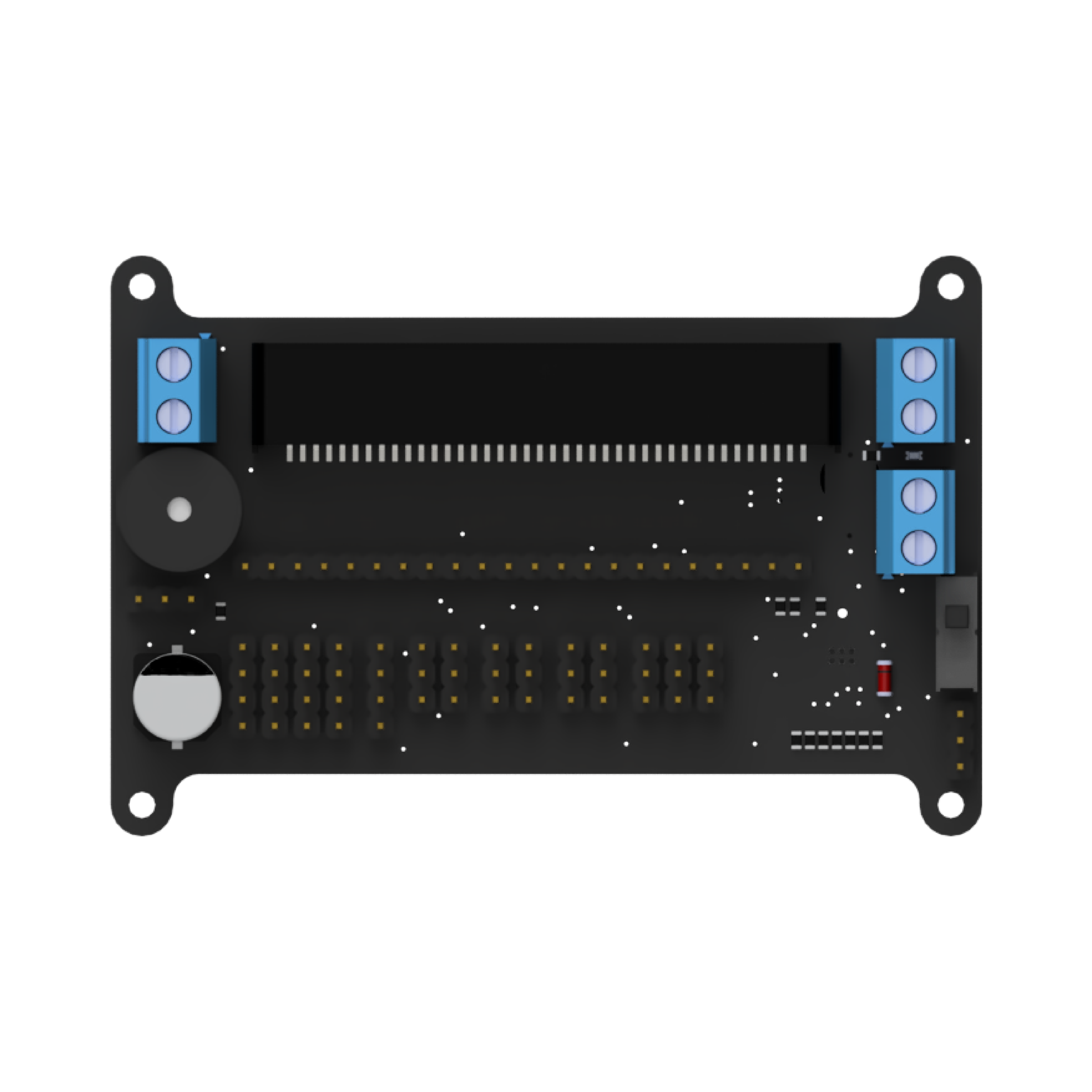
Now we can move on to the IO Expander, which is located on our mainboard. The IO Expander is an I2C interface to which our sensors are mainly connected. The IO Expander extends the pins of the micro:bit so that it is possible to use all the sensors of the Joy-Car.
You can find out more about the IO Expander here.
In the following example, you can read out the IO Expander and write to the available pins accordingly. It is important to note the differences between the various revisions of the IO Expander. Further information on the revisions can be found here.
Differences between the revisions:
- Revision 1.3: Pins 0, 1, and 7 are free and can be written to
- Older revisions: Only pin 7 is free and can be used
In the example, pin 7 of the IO Expander is first switched to LOW and then reset to HIGH. The IO expander is then read out every second in an endless loop in order to continuously monitor the current status of the pins.
Revision
Read IO Expander

This code block reads the IO expander and returns the values determined as a string. In this string, the first number represents the status of pin 0. The remaining numbers in the string correspond to the states of the other pins in the order in which they are numbered.
The returned data has the following structure:
- Left speed sensor
- Right speed sensor
- Left line tracker
- Middle line tracker
- Right line tracker
- Left obstacle sensor
- Right obstacle sensor
- Free pin 7
- Free pin 0 (only available from revision 1.3)
- Free pin 1 (only available from revision 1.3)
This makes it easy to check and process the pin statuses in a readable and structured form.
Write to IO Expander
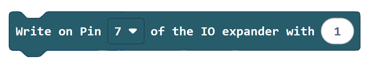
This code block can be used to write to the free pins of the IO expander by setting them to HIGH or LOW. Please note that the availability of the free pins depends on the revision of the Joy-Car. Further information on the differences between the revisions can be found here. The code takes these differences into account and ensures that only the pins that are released for the respective revision are written.
Code example
JoyCar.initJoyCar(RevisionMainboard.OnepThree)
JoyCar.writeIOExpander(IOExpanderPin.Pin7, 0)
serial.writeLine(JoyCar.readIOExpander())
basic.pause(1000)
JoyCar.writeIOExpander(IOExpanderPin.Pin7, 1)
serial.writeLine(JoyCar.readIOExpander())
basic.pause(1000)
basic.forever(function () {
    serial.writeLine(JoyCar.readIOExpander())
    basic.pause(1000)
})Revision & initialization
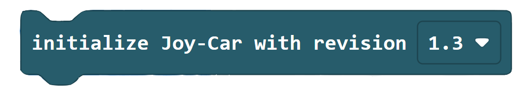
First, the revision of the Joy-Car must be defined to ensure that the following methods are correctly adapted to the respective version of the Joy-Car. You can find the revision number of your Joy-Car here. This revision number is simply entered in the joycar_rev variable.
The IO Expander is then initialized so that it can be used for the next steps in the program. Initialization enables communication with the IO Expander and ensures that the pins can be configured according to the defined revision.
# Define your Joy-Car mainboard revision
joycar_rev = 1.3

# Initialization of the I2C interface for the Joy-Car mainboard
i2c.init(freq=400000, sda=pin20, scl=pin19)
Read IO Expander
The fetchSensorData method is used to read out the IO Expander and write the captured data to an array called bol_data_dict. This array is then returned. The method adapts the assignment of the data to the revision of the Joy-Car.
In revisions as from 1.3, the speed sensors are no longer connected to the IO expander. Instead, the 8th and 9th positions in the array represent the states of the free pins pin 0 and pin 1. The 0th and 1st positions remain assigned to the speed sensors.
The returned data in the array has the following structure:
- Left speed sensor
- Right speed sensor
- Left line tracker
- Middle line tracker
- Right line tracker
- Left obstacle sensor
- Right obstacle sensor
- Free pin 7
- Free pin 0 (only available from revision 1.3)
- Free pin 1 (only available from revision 1.3)
This structure ensures that all sensor data and free pins are clearly and unambiguously assigned, regardless of the revision used.
# retrieve all sensor data
def fetchSensorData():
    # Since the zfill function is not included in micro:bit Micropython,
    # it must be inserted as a function
    def zfill(s, width):
        return '{:0>{w}}'.format(s, w=width)

    # Read hexadecimal data and convert to binary data
    data = "{0:b}".format(ord(i2c.read(0x38, 1)))
    # Fill in the data to 8 digits if required
    data = zfill(data, 8)
    # declare bol_data_dict as dictionary
    bol_data_dict = {}
    # Counter for the loop that enters the data from data into bol_data_dict
    bit_count = 7
    # Transfer the data from data to bol_data_dict
    for i in data:
        if i == "0":
            bol_data_dict[bit_count] = False
            bit_count -= 1
        else:
            bol_data_dict[bit_count] = True
            bit_count -= 1

    # As of mainboard revision 1.3, the speed sensors are on separate pins
    if joycar_rev >= 1.3:
        bol_data_dict[8], bol_data_dict[9] = bol_data_dict[0], bol_data_dict[1]
        bol_data_dict[0] = bool(pin14.read_digital())
        bol_data_dict[1] = bool(pin15.read_digital())

    # bit 0 = SpeedLeft, bit 1 = SpeedRight, bit 2 = LineTrackerLeft,
    # bit 3 = LinetrackerCenter, bit 4 = LinetrackerRight,
    # bit 5 = ObstacleLeft, bit 6 = ObstacleRight, bit 7 = free pin(7)
    # (bit 8 = free (pin0) bit 9 = free (pin1)) - only with revision 1.3 or newer
    return bol_data_dict
Write to IO Expander
The writeIOExpander method allows you to set the free pins of the IO expander to HIGH or LOW. Thereby:
pin: is used to select the specific pin to be written to.value: specifies whether the pin is set toHIGH(1) orLOW(0).
The method takes into account the respective revision of the Joy-Car to ensure that only the permitted pins can be written to:
- From revision 1.3: Pins 0, 1 and 7 can be written to.
- Before revision 1.3: Only pin 7 is available.
This method ensures that no unauthorized pins are changed and at the same time allows flexible and safe control of the pins independently of the Joy-Car revision.
# Write data to IO expander as byte
def writeIOExpander(pin, value):
    # Read the current status from the IO expander
    expander_state = ord(i2c.read(0x38, 1))
    # Newer versions than 1.3 have 3 possible pins to use (0, 1 and 7)
    # With older versions, only pin 7 can be used freely.
    # Input pins are set to the value 1.
    if joycar_rev < 1.3:
        if pin == 7:
            if value == 1:
                i2c.write(0x38, bytes(str(chr(expander_state | 0x80 | 0x7F)), 'ascii'))
            elif value == 0:
                i2c.write(0x38, bytes(str(chr((expander_state & 0x7F) | 0x7F))
                                      , 'ascii'))
    if joycar_rev >= 1.3:
        if pin == 0:
            if value == 1:
                i2c.write(0x38, bytes(str(chr(expander_state | 0x01 | 0x7C)), 'ascii'))
            elif value == 0:
                i2c.write(0x38, bytes(str(chr((expander_state & 0xFE) | 0x7C))
                                      , 'ascii'))
        elif pin == 1:
            if value == 1:
                i2c.write(0x38, bytes(str(chr(expander_state | 0x02) | 0x7C), 'ascii'))
            elif value == 0:
                i2c.write(0x38, bytes(str(chr((expander_state & 0xFD) | 0x7C))
                                      , 'ascii'))
        elif pin == 7:
            if value == 1:
                i2c.write(0x38, bytes(str(chr(expander_state | 0x80 | 0x7C)), 'ascii'))
            elif value == 0:
                i2c.write(0x38, bytes(str(chr((expander_state & 0x7F) | 0x7C))
                                      , 'ascii'))
Code example
# Import necessary libraries
from microbit import *

# Define your Joy-Car mainboard revision
joycar_rev = 1.3

# Initialization of the I2C interface for the Joy-Car mainboard
i2c.init(freq=400000, sda=pin20, scl=pin19)

# retrieve all sensor data
def fetchSensorData():
    # Since the zfill function is not included in micro:bit Micropython,
    # it must be inserted as a function
    def zfill(s, width):
        return '{:0>{w}}'.format(s, w=width)

    # Read hexadecimal data and convert to binary data
    data = "{0:b}".format(ord(i2c.read(0x38, 1)))
    # Fill in the data to 8 digits if required
    data = zfill(data, 8)
    # declare bol_data_dict as dictionary
    bol_data_dict = {}
    # Counter for the loop that enters the data from data into bol_data_dict
    bit_count = 7
    # Transfer the data from data to bol_data_dict
    for i in data:
        if i == "0":
            bol_data_dict[bit_count] = False
            bit_count -= 1
        else:
            bol_data_dict[bit_count] = True
            bit_count -= 1

    # As of mainboard revision 1.3, the speed sensors are on separate pins
    if joycar_rev >= 1.3:
        bol_data_dict[8], bol_data_dict[9] = bol_data_dict[0], bol_data_dict[1]
        bol_data_dict[0] = bool(pin14.read_digital())
        bol_data_dict[1] = bool(pin15.read_digital())

    # bit 0 = SpeedLeft, bit 1 = SpeedRight, bit 2 = LineTrackerLeft,
    # bit 3 = LinetrackerCenter, bit 4 = LinetrackerRight,
    # bit 5 = ObstacleLeft, bit 6 = ObstacleRight, bit 7 = free pin(7)
    # (bit 8 = free (pin0) bit 9 = free (pin1)) - only with revision 1.3 or newer
    return bol_data_dict

# Write data to IO expander as byte
def writeIOExpander(pin, value):
    # Read the current status from the IO expander
    expander_state = ord(i2c.read(0x38, 1))
    # Newer versions than 1.3 have 3 possible pins to use (0, 1 and 7)
    # With older versions, only pin 7 can be used freely.
    # Input pins are set to the value 1.
    if joycar_rev < 1.3:
        if pin == 7:
            if value == 1:
                i2c.write(0x38, bytes(str(chr(expander_state | 0x80 | 0x7F)), 'ascii'))
            elif value == 0:
                i2c.write(0x38, bytes(str(chr((expander_state & 0x7F) | 0x7F))
                                      , 'ascii'))
    if joycar_rev >= 1.3:
        if pin == 0:
            if value == 1:
                i2c.write(0x38, bytes(str(chr(expander_state | 0x01 | 0x7C)), 'ascii'))
            elif value == 0:
                i2c.write(0x38, bytes(str(chr((expander_state & 0xFE) | 0x7C))
                                      , 'ascii'))
        elif pin == 1:
            if value == 1:
                i2c.write(0x38, bytes(str(chr(expander_state | 0x02) | 0x7C), 'ascii'))
            elif value == 0:
                i2c.write(0x38, bytes(str(chr((expander_state & 0xFD) | 0x7C))
                                      , 'ascii'))
        elif pin == 7:
            if value == 1:
                i2c.write(0x38, bytes(str(chr(expander_state | 0x80 | 0x7C)), 'ascii'))
            elif value == 0:
                i2c.write(0x38, bytes(str(chr((expander_state & 0x7F) | 0x7C))
                                      , 'ascii'))

# Set additional pin 7 to low
writeIOExpander(7, 0)
print(fetchSensorData())
sleep(1000)

# Set additional pin 7 to high
writeIOExpander(7, 1)
print(fetchSensorData())
sleep(1000)

while True:
    # Output retrieved data
    print(fetchSensorData())
sleep(1000)Revision
Read IO Expander
This code block reads the IO expander and returns the values determined as a string. In this string, the first number represents the status of pin 0. The remaining numbers in the string correspond to the states of the other pins in the order in which they are numbered.
The returned data has the following structure:
- Left speed sensor
- Right speed sensor
- Left line tracker
- Middle line tracker
- Right line tracker
- Left obstacle sensor
- Right obstacle sensor
- Free pin 7
- Free pin 0 (only available from revision 1.3)
- Free pin 1 (only available from revision 1.3)
This makes it easy to check and process the pin statuses in a readable and structured form.
Write to IO Expander
This code block can be used to write to the free pins of the IO expander by setting them to HIGH or LOW. Please note that the availability of the free pins depends on the revision of the Joy-Car. Further information on the differences between the revisions can be found here. The code takes these differences into account and ensures that only the pins that are released for the respective revision are written.
Code example
JoyCar.initJoyCar(RevisionMainboard.OnepThree)
JoyCar.initController(ControllerType.Calliope)
JoyCar.writeIOExpander(IOExpanderPin.Pin7, 0)
serial.writeLine(JoyCar.readIOExpander())
basic.pause(1000)
JoyCar.writeIOExpander(IOExpanderPin.Pin7, 1)
serial.writeLine(JoyCar.readIOExpander())
basic.pause(1000)
basic.forever(function () {
    serial.writeLine(JoyCar.readIOExpander())
    basic.pause(1000)
})